Guide
Designing your items
When manufacturing through cutting machining, there are some aspects that can be good to keep in mind when designing. In general, we can say that it is preferable as far as possible to design with radii and diameters with a full millimeter pitch, or alternatively half a millimeter. If you use tenths of a millimeter, special tools are usually required and the product becomes more expensive.
Below are some simple recommendations and how we handle some practical problems we may encounter in a design. We use a very simple model to visually show what we mean by the different categories.
Pockets
When designing pockets in your model, it can be good to keep in mind the depth of them in relation to how big the cutter you can go down with. In general, the depth of the pockets is up to 3 times the diameter of the largest cutter that can fit, to be seen as standard. Up to 4 times the diameter is usually possible, but with significantly lower cutting data and thus longer processing time and more expensive detail as a result. For depths over 4 times the diameter, it will be difficult to answer in general, without something that must be checked from case to case, and any need for special tools.
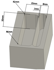
Example picture of a 3D model
The example here shows two pockets both 35mm deep. One is 25mm wide while the other is 8mm wide. The widest pocket is ok to manufacture as you can, for example, use a Ø12mm cutter that reaches 36mm deep. While the 8mm pocket is not ok as a standard Ø8mm cutter reaches a maximum of 24mm deep.
Inner corner radii
When designing pockets in a detail, it is also important to think about inner corner radii, these should not be smaller than the radius of the cutter required to make the pocket deep enough. As in the figure above, there are examples where one corner has a radius of 2mm and the others have a radius of 6mm. The 2mm radius becomes difficult to implement as you need a 12mm cutter to get to the bottom of the pocket, while the 6mm radius will not be a problem with a 12mm cutter.
Inner corner wall-bottom
Sharp (90 °) inner corner between “wall and floor” in eg a pocket, we can not mill. All inner corners that are designed 90 ° have a 45 ° phase as standard with a width of 0.05–0.3 mm depending on the size of tools required for the part.
Thin walls
Details that have thin-walled elements in them, can create problems during manufacture as the walls can start to vibrate and destroy tools or generate bad surfaces. There are no easy answers to what works and not because it depends on many factors, but in general we recommend that you try to have 1mm as the minimum wall thickness. The figure above shows a thin wall that has the dimension 1mm, this is the smallest dimension that we recommend in order to achieve a good result.
Hole drilling
In general, holes with a maximum of Ø16mm are ok to drill to depths of up to 8 times the diameter. For holes> Ø16mm, apply 5 times the diameter. Holes deeper than this must be examined for each case. Bottom holes up to Ø16mm that are designed with a flat bottom, get the full diameter as standard for the designed bottom, then there is a 120 ° -145 ° conical impression from the drill bit.
Threading
For threading, it applies as standard that the thread length can be 2-3 times the diameter, however, you can access as far down as to 8 times the diameter, but it then requires that you initially have a larger hole and then go down to thread diameter.
Sharp outer corners & edges
Outer corners and edges that are designed sharp, we possibly put a 0.5mm phase in manufacturing, this to avoid sharp edges.